Facilities and Equipment
Equipment
- 4K Test Facility
- Alpha Counter
- Chemical Purification Facility
- Computing Facility
- HPGe (High Purity Germanium) Detectors
- Low Temperature Refrigerators
- NaI Crystal Growing Facility
- Oxide Crystal Growing Facility
4K Test Facility
4K test setup at CUP (IBS)
The Center for Underground Physics (CUP) has a series of projects running or being planned for searching dark matter and neutrino-less double beta decay at down-to cryogenic temperatures (~10 mK). Among them, two major experiments are AMoRE (Advanced Mo-based Rare process Experiment) and COSINE-LT (COSINE at Low Temperature searching for dark matter). The AMoRE has been using 100Mo based CaMoO4 crystals with a mass of ~6 kg at currently running experiment setup, called AMoRE-Pilot, to understand its cryogenic detectors and background levels from outside and inside of the detectors. The project is preparing an upgraded experiment by increasing total mass of crystals and reducing the background levels. But the final crystal is not decided yet for a relatively huge mass of ~200 kg. For R&D purposes, it is necessary to study different crystals’ properties at room and low temperatures. Most of Mo based crystals have very low or no light yield at room temperature due to its high thermal quenching behavior. But studying crystals’ properties at mK temperatures has challenges such as time (several days to weeks to prepare one crystal sample into a detector) and a rather complicated test setup. Also the COSINE-LT is being planned to run its experiment in low temperatures to reduce thermal noises in electronics and to have more light yields. From other experimental results at low temperatures for a NaI(Tl) crystal, light quenching also observed to occur in different temperatures. In order to optimize the quenching temperature for the NaI(Tl) crystal, it is necessary to study the crystal’s properties at low temperatures.
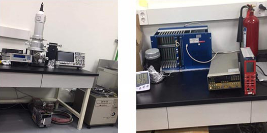
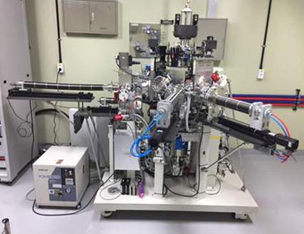
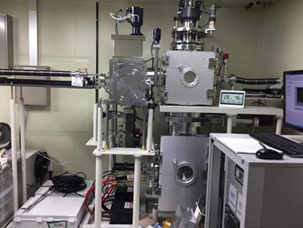
With these aims, the CUP has established a 4K test setup. For cooling down a crystal sample, liquid Helium is used as a coolant in a compressor. For studying luminescence properties, several excitation sources are available such as 266 nm UV Laser, 280 nm UV LED, 260 nm UV LED. Moreover, scintillation characterization of the crystals can be studied with several radioactive sources. A few pictorial views of the setup are shown in Fig. 1. A specification of the CUP 4K setup is also summarized in Table 1.
-
Figure 1 :
4 K test setup at CUP, Cryostat (left) and DAQ (right).
Table 1. Summary of the 4 K test setup specification at the CUP.
| Measurable crystal size | TemperatureRange (K) | Ramping up/down speed modes | Available sources | DAQ sampling rate |
|---|---|---|---|---|
| Length (8-10 mm) Width (2-10 mm) Height (8-12 mm) |
4 – 320 | High (1.5 h from room temp. to 6 K)MediumLow | UVLED 260 nmUVLED 280 nmLaser 266 nm662 keV gamma (137Cs) | 400 MS/s |
Here are brief explanations on scintillation and quenching which were mentioned in the above. Scintillators convert a fraction of energy lost by moving charged particles in the form of photons. Conversion of incident radiation energy to photons involves many subsequent processes which may reduce the scintillator’s efficiency. Quenching refers to non-radiative energy transfer process, which decreases light yield of the material. Among several quenching mechanism, main is thermal quenching. Thermal quenching is a reduction in efficiency of scintillation as temperature increases due to a competition of non-radiative relaxation process with radiative process.
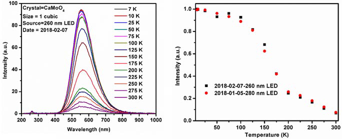
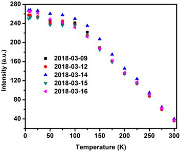
We have some results with this experimental setup for CaMoO4 crystals which are grown by CUP and NIIC (Nikolaev Institute of Inorganic Chemistry SBRAS, Russia) and the results are presented in Figs. 2 and 3. From the results, we concluded that it works quite consistently.
-
Figure 2 :
Luminescence spectra measurements of a CaMoO4 (NIIC) crystal in a temperature range of 7 – 300 K with a 260nm LED (left). Normalized peak intensities of a CaMoO4 crystal measured with two different energy LED sources. (right).
-
Figure 3 :
Peak intensities of a CaMoO4 (CUP) crystal measured with a 280 nm LED source in different days to see the stability of the measurements in the setup.
We also have the same low temperature setup at Kyungpook National University (KNU) (Prof. HongJoo Kim, a collaborator member of the CUP), but it can reach down to only 10 K. Recently we have published several results based on crystals characterized in that setup [1,2,3,4].
Reference
- 1Indra Raj Pandey, H.J. Kim, Y.D. Kim, J Cryst Growth. 480, 62 (2017).
- 2Indra Raj Pandey, Sujita Karki, H. J. Kim, Y. D. Kim, M. H. Lee, and N. V. Ivannikova, IEEE Trans. Nucl. Sci. 65, 2125 (2018).
- 3Indra Raj Pandey, H.J. Kim, H.S. Lee, Y.D. Kim, M.H. Lee, V.D. Grigorieva, V.N. Shlegel, Eur. Phys. J C 78, 973 (2018).
- 4J. K. Son, Indra Raj Pandey, H. J. Kim, Y. D. Kim and M. H. Lee, IEEE Trans. Nucl. Sci. 65, 2120 (2018).
Alpha Counter
UltraLo-1800 alpha particle counter
-
Figure 1 :
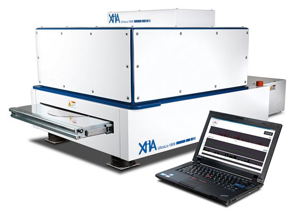
XIA UltraLo-1800 system.
The argon-filled ionization chamber uses vertical electric field to drift free electrons created by alpha particle’s interaction with gas molecules. Large sample area and pulse-shape discrimination allow the counter to measure alpha particles as low as 1.0*10-4∕cm2∕hr level. This image is from Ref.
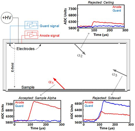
The UltraLo-1800 shown in Fig. 1 from XIA is an ionization chamber system filled with pure argon gas for detecting alpha particles in a sample. The size of the ionization chamber is 1800 cm2 in area and 15 cm in height. A uniform electric field about 70 V/cm is applied between the electrodes and the tray. The detector consists of two positively biased electrodes called anode and guard at the upper part of the chamber and a grounded sample tray at the bottom (see Fig. 2).
The principle of alpha detection in the chamber is based on Schokley-Ramo theorem. When a charged particle ionizes gas molecules in the chamber, ion pairs (Ar+,e–) are produced along its path. Then, when the electrons drift through the field, according to the theorem, an induced charge on an electrode is proportional to the potential difference from the start to the end of the passage of the produced electron.
Since a distance from the produced electrons, i.e. alpha particle’s location, to the electrode determines the pulse shape of the signal, the Ultralo-1800 discriminates alpha particles emitted from the sample surface from those emitted from other areas of the chamber volume (see α1, α2, and α3 in Fig. 2).
-
Figure 2 :
A simplified view of background discrimination in the chamber.
Alpha particles originating from different areas in the chamber can be vetoed by using pulse shapes and amplitudes in two electrodes. α1 is a sample signal showing high anode and flat guard signal if it occured in the middle. α2 started on the ceiling and so it shows little signal due to charge induction. α3 shows large guard signal relative to the anode signal because the event occurred at the sidewall. This image is from Ref.
Specification of the UltraLo-1800 counter
Table 3 shows the physical specification of the counter. The size of the detector is 165 cm × 89 cm × 69 cm (L × W × H, in operation) and 241 cm × 89 cm × 117 cm (fully opened). The detector uses pure argon boiled off from liquid as the ionization gas and consumes about 5 L/min during measurement. Nitrogen gas can be used alternatively without any degrade in performance.
Table 1: System specifications of the UltraLo-1800 counter. These numbers are from Ref.
| System Requirement | Specification |
|---|---|
| Sample size (min.-max.) | 707-1800 cm² |
| Sample thickness (max.) | 6.3 mm |
| Sample weight (max.) | 9 kg |
| Counting gas | Argon |
| Gas pressure | (21±1) psi |
| Line voltage | 100-240 V,50/60 Hz |
| Power consumption (max.) | 100 W |
| Dimension (L×W×H) | (165 cm×89 cm×69 cm) |
| Weight | 163 kg |
Detector Test
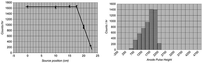
IBM performed several tests with 210Pb alpha/beta source (~5.3 MeV alpha end point and ~1.2 MeV beta end point) placed at the center of the tray. First of all, an IBM’s test showed the XIA counter is not sensitive to the beta particles. Secondly, Figure 3 shows count rate against horizontal location from the source to evaluate the signal efficiency especially near the edge of the sample area. As can be seen on the left plot, the rate did not decrease until 17 cm from the center. Note that the counter area is a square with 48 cm at one side (roughly 24 cm from the center). Finally, on the right plot, energy resolution using pulse height as a energy proxy is estimated to be better than 9% FWHM at 4.6 MeV.
-
Figure 3 :
Count rate using a 210Pb as a function of location for efficiency and pulse height for a resolution estimate.
Figure (a) shows decrease in counting efficiency near the edge of the counter area beyond 17 cm. Figure (b) shows the pulse height distribution for 210Pb source. Note that the peak corresponds to 5.4 MeV alpha particles from the source and the spread in the distribution is an energy resolution. Both figures are from Ref.
Performance of UltraLo-1800
The detector is used for screening materials with an emissivity (ϵ) measure defined as alpha particle counts per hour in cm². The UltraLo-1800 applies event classification techniques using both rise time and signal amplitude to reach background rates to ϵ < 1.0 × 10⁻⁴∕cm²∕hr. Alpha particles originated from the top and the sidewalls can be discriminated from those in the sample. For a comparison, the conventional proportional counter systems can measure the emmissivity up to ϵ ~ 1.0 × 10⁻³∕cm²∕hr. Additionally, the background suppression allows the XIA chamber to measure samples faster than other alpha counters. For exammple it measures emissivites in the range ϵ = 0.001 – 0.0005∕cm²∕hr within 10 hours and emissivities ϵ ~ 0.0005∕cm²∕hr within 100 hours.
In 2009, IBM measured alpha emissivities of an ultra-low sample at (6.0 ± 1.0) × 10-4∕cm²∕hr using the XIA detector in a 5-day running. More recently in 2015, the XMASS experiment reported 12-day XIA measurement of ultra-low level Cu at (1.4 ± 0.3) × 10-4∕cm²∕hr.
Table 2: Performance specifications of the UltraLo-1800 counter. These numbers are from Ref.
| Peformance | Specification |
|---|---|
| Counting time for ϵ = 0.001 (α∕cm²∕hr) | (50%) 6-hr run |
| where ϵ is the emissivity | (12.5%) 90-hr run (accuracy) |
| Efficiency | >90% of 2π |
| Resolution at 4.6 MeV | <9% FWHM |
| Measurement range | 1 - 10 MeV |
Plan for alpha measurements at CUP
The alpha counter is scheduled to arrive to CUP at mid-May. We plan to install the counter at the test room at Y2L shown in Fig. 4. Reduced cosmic-ray muon rate, low foot traffics, and low noise sources are the main advantageous for the alpha measurement. The XIA counter can fit in the room (10 m² in area 3 m in height) comfortably.
The detector is mainly for the powder screening, especially for NaI crystal powders. Therefore, a special techniqure should be developed for the powder measurements. We would also like to develop a method about how to improve the current sensitivity. Additional clean facilities including radon free air would allow us to avoid sample contamination to radon-induced alpha particles.
Figure 4: XIA alpha counter installation layout at Y2L. The room is located at the A5 tunnel end side. The room has an area of about 10 m⊃ with 3 m height. Gray area represents tunnel rock walls. The counter is to be installed on the vibration-free desk at the wall side of the room. Once the counter moves in, the main front door will be sealed to minimize foot traffics. The remaining area will be used for sample preparation and analysis. Radon-free air and/or clean room facilities are expected to be installed.
For the first setup, we plan to run a few calibration measurements using a point alpha source with known energy. This is to obtain efficiency in detection area. We also like to measure several background data without any source or any sample to figure out the intrinsic background radioacitivity. Measurement plan is summarized in Table 3.
Table 3: Measurement plan
| Measurements | Note |
|---|---|
| Efficiency scan with 241Am source | area calibration |
| w/ and w/o powder cover | aluminzed Mylar 5 μm |
| tray only | - |
| pure Copper | PNNL sample |
| pure Copper with cleaning | - |
| NaI powder | - |
| NaI film | from NaI powder |
Sample Preparation
Although the counter can identify alpha particles of the sample easily, a few steps need to be in place before running the counter. The main challenge is how to prepare the NaI(Tl) powder sample. Since the powder may not be placed in the tray as is, we either make a thin film from NaI(Tl) solution on the tray, make a pallet of NaI(Tl) from powder, or use aluminized Mylar cover to avoid powder particulates from flying and possibly contaminating inside of the detector.
Chemical Purification Facility
When the center started, the purification group was formed to explore purification techniques to produce radiopure materials such as NaI powder for COSINE and MoO3, CaCO3, and LiCO3 powders for AMoRE.
NaI crystals for COSINE were previously grown from highly pure NaI powder by the Bridgman-Stockbarger technique. During the growing process, contaminations from the ambient environment are highly suppressed. In order to grow a NaI crystal with ultralow radioactivities from 40K, 210Pb, 228Tl, 226Ra, etc., it is necessary that the initial NaI powder is radiopure. We studied several purification techniques to obtain radiopure NaI powder. Among the several techniques, we found that the recrystallization method is more effective than others and can be applied for bulk purification of NaI powder.
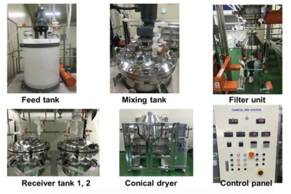
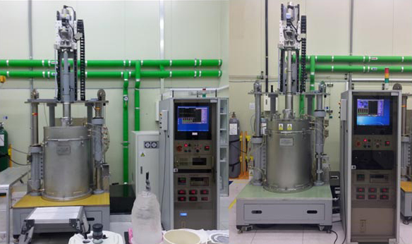
Based on our 1 kg scale powder purification study, we designed and built a system to purify ~70 kg of powder, requiring clean and tight connections between each unit, and easy maintenance and control of the entire system. This system consists of the following units,
- Feed tank : NaI powder is dissolved into DI water inside this tank, and NaI solution is moved to the mixing tank.
- Mixing tank : Recrystallization for the solution is applied in this tank by heating to 130 °C and then cooling down to room temperature. After this process, there are NaI crystals and solution.
- Filter unit : NaI crystals and solution are separated by the filer, and solution is moved to one of the receiver tanks.
- Two receiver tanks : Collect liquid wastes from mixing tank, filter, unit and conical dryer.
- Conical dryer : NaI crystals from the filter unit are dried inside the dryer and we collect the final product, purified NaI power.
- Control panel : It controls all adjustable system parameters such as temperature, pressure, rotation speed of the dryer, engagement of the stirrer, etc.
Figure I-31 and figure I-32 show each unit and the purification system.
-
Figure I-31 :
Photos for each unit.
-
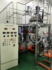
Right view of NAL Purification facility
-
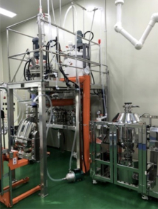
Left view of NAL Purification facility
-
Figure I-32 :
The NaI purification system.
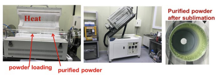
For AMoRE, The Mo-based crystals, CaMoO4, Li2MoO4, Na2Mo2O7, etc., are required to have radioactivity levels below ~10 μBq/kg for 228Th and 226Ra. In order to achieve such a goal, we developed sublimation equipment for MoO4 powder purification as shown in Figure I-33. This equipment has several features as follows,
- It has a quartz tube about 1.5 m long; the vacuum is maintained in the tube with 10 mTorr during operation.
- Cylindrical crucible for powder loading and collecting purified powder.
- It has three heating zones; the temperature of each zone can be raised up to 1000 °C.
- The heating part can be tilted up to 60 °
In purification with the sublimation method, the powder is loaded in the bottom part of the crucible and the crucible is placed inside the quartz tube. By heating to about 710 °C, sublimated MoO3 moves to the upper part of the crucible.
-
Figure I-33 :
Sublimation equipment.
Powder is loaded into the bottom part of quartz crucible inside the quartz tube before operation (left). During operation, the quartz tube is tilted in 10° (middle). Purified powder is collected in the upper part of quartz crucible (right).
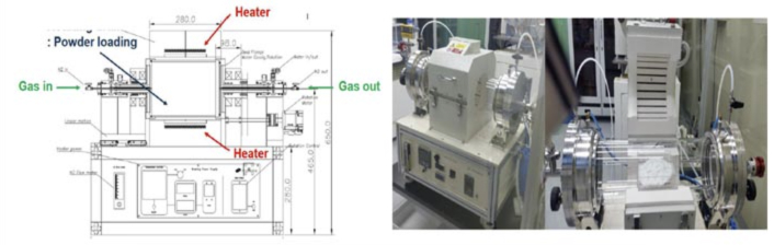
Powder that has purified by sublimation contains MoxOy (x, y=1,2,3…) forms, which cannot be used to grow a crystal. Before converting MoxOy into MoO3, the MoxOy powder must be dissolved with aqua-ammonia, producing an aqueous solution containing ammonium molybdate (NH4)2Mo4O4. By blowing hot air inside the annealing furnace (see Figure I-34), this solution is heated to about 680 °C, producing MoO3 powder.
-
Figure I-34 :
Annealing furnace. Schematic diagram (left) and the furnace (right).
Computing Facility
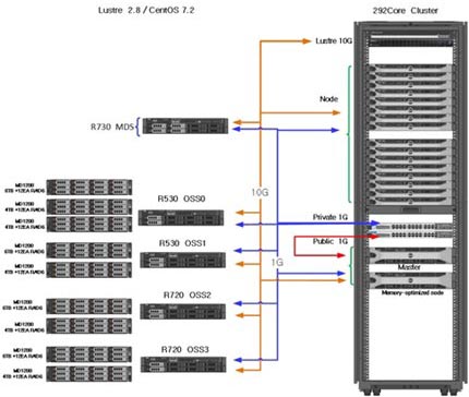
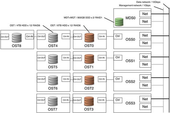
CUP requires a high performance computing facility to support Monte Carlo simulations and large-scale data analysis for all CUP experiments. These needs are met primarily by the CUP computing cluster (Figure I-35) which consists of 1 master node, 16 work nodes, and 1 memory-optimized work node, each with 16 to 20 core processors and 292 core processors in total. It provides data storage including two 800-gigabyte solid state drives and a 400-terabyte Lustre parallel file server, as shown in Figure I-36. Access to the data storage is provided over a 10 Gb/s network.
-
Figure I-35 :
CUP cluster configuration
-
Figure I-36 :
Lustre storage configuration
HPGe (High Purity Germanium) Detectors
High Purity Germanium detector (HPGe) system
High Purity Germanium (HPGe) detectors as a semiconductor detector are used to analyze activities of radioactive isotopes in materials by measuring gamma rays from the isotopes. In Center for Underground Physics (CUP), there are two single p-type coaxial detectors made of one HPGe crystal with 100% relative efficiency each, Canberra Coaxial 1 & 2(CC1 & CC2), and an array detector with fourteen HPGe crystals with 70% relative efficiency each at Y2L.
-
-
Figure 1 :
CC1 HPGe detector
-
Figure 1 :
-
-
Figure 2 :
CC2 HPGe detector
-
Figure 2 :
-
-
Figure 3 :
Array HPGe detector
-
Figure 3 :
CC1 & CC2 single HPGe detector
The YangYang Underground Laboratory is placed in YangYang pumped storage power Plant and there are lots of background gamma-ray signals coming from the rocks surrounding the experiment place. To reduce the background signals, we installed lead and copper shielding systems in reliable geometries.
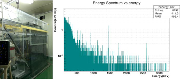
CC1 installed in 2010 at A6 laboratory is shielded from outside to inside by 10 cm-thick Pb layer for top and bottom, 15 cm-thick Pb layer for sides and 10 cm-thick Cu layer for all the innermost sides. In 2015, 5 cm-thick ancient lead was installed near the HPGe detector to reduce β-decays and bremsstrahlung backgrounds of 210Pb which has 22.2 y half-life. The background count rate of the CC1 is 0.0079 Hz in an energy range of 50 ~ 4000 keV.
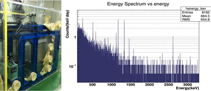
Likewise, CC2 installed in 2016, is shielded from inside to out by a layer of 10 cm thick copper, followed by 10 cm thick lead produced by the J. L. Goslar company, and a generically-sourced lead with 10 cm thickness. The background count rate of the CC2 is 0.0073 Hz in an energy range of 50 ~ 3200 keV.
Both detectors have sensitivities to 228Th and 226Rn of about 1 mBq/kg for samples on a scale of about one kg and counting time of roughly two weeks. A similar condition produces 40K sensitivity of about 5 mBq/kg. They are rough estimates and depend greatly on a number of factors that vary from sample to sample.
-
Figure 4 :
CC1 detector with shielding system (left), background spectrum (right)
-
Figure 5 :
CC2 detector with shielding system(left), background spectrum (right)
Array HPGe detector system
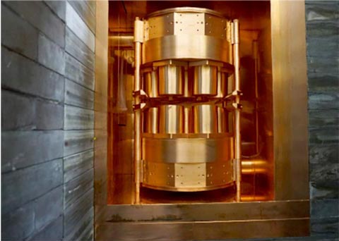
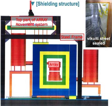
In early 2017, the CUP installed an array of fourteen 70% HPGe detectors composed of two arrays facing each other and each array has seven p-type coaxial HPGe detectors. The device is being used to study rare decays (i.e. decay of 180mTa) and to reach new sensitivity levels for background assays. By screening several candidate materials for the components using the single HPGe (CC1 mostly) detectors and studying backgrounds in different configurations using simulation tools, the CUP has developed it in collaboration with CANBERRA. The array detector is shielded, from inside to out, by a layer of 10 cm thick copper, followed by 10 cm thick lead produced by the J. L. Goslar company, and further 20 cm thick generically-sourced lead. The shielding system has 2 doors on two sides with a motor system to open for a replacement of samples. To prevent other particles, especially radon, enter through the door gaps, Vikuiti sheets were sealed and dry nitrogen gas from boil-off of liquid nitrogen is supplied continuously. The background count rate of the Array is 0.062 Hz in an energy range of 50 ~ 4000 keV for all fourteen detectors. Compared with the CC1 for the same relative efficiency, the background count rate of the array detector is reduced by 25%, therefore, the array detector is suitable to measure more sensitive samples.
-
Figure 6 :
Array detector in a shielding system
-
Figure 7 :
A schematic of the Array detector in a cross-section view
Reference
- E. Sala et al., “Development of an underground low background instrument for high sensitivity measurements,” J. Phys.: Conf. Ser (2016) 062050.
- E. Lee et al.,”Measurements of detector material samples with two HPGe detectors at the YangYang Underground Lab.,” PoS(ICHEP2018)809
- G. Kim et al., “DAQ optimization, signal processing and simulations for an ultra low background HPGe detectors Array,” LRT 2017 Poster
- S. Park et al., “An enriched Mo-100 powder measurement by a HPGe array detector,” PoS(ICHEP2018)783
- M. H. Lee et al., “An ultra-low radioactivity measurement HPGe facility at the Center for Underground Physics,” PoS(ICHEP2018)363
Low Temperature Refrigerators
Since the heat and light signals of the AMoRE experiment are very weak, it is impossible to measure the signals at room temperature. In order to achieve the high sensitivity and low threshold, CUP employs thermal calorimetric detection at milli-Keven temperatures as the main detection technique. The calorimeters operate well below 1 K. Refrigerators and cryostats are essential equipment not just to perform the main AMoRE experiment but also to test and characterize necessary sensors and detector modules. CUP has built up three types of refrigerators based on their base temperatures. First low temperature screening tests are done in liquid helium storage dewars and 4K refrigerators. Key parameters of metallic magnetic calorimeters (MMCs) are characterized below 1 K. Adiabatic demagnetization refrigerators are a convenient cooling system to provide 30-100 mK working temperatures. Complete detector modules including an absorber crystal and an MMC sensor with a SQUID are tested using dilution refrigerators that can realize a constant temperature down to 10 mK for long-time continuous measurement.
4K systems (dipping probes and PTR refrigerator)
-
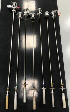
Figure I-6 :
4K dipping probes
The main detector technology used in the low temperature calorimeters of AMoRE has been developed based on superconducting sensors and electronics. We use niobium-based sensors that have their superconducting transition temperature near 9 K. Basic characterization of the superconducting sensors requires frequent 4K tests. Basic screening is carried out for working devices at the temperature. Moreover, during their R&D stages, each fabrication procedure has been followed by a series of basic performance test at 4K.
The dipping probe method is the most convenient way of performing tests at 4K. One can insert a dipping probe with attached test sensors into a liquid-helium storage dewar. As shown in Figure I-6, we have made several 4 K dipping probes in our own design including vacuum conduction cooling probes. These probes are in heavy use. The transition temperatures and critical current of niobium patterns are tested with these probes. Moreover, they are used for low temperature resistivity measurement of metal films used as phonon collectors on crystals and light detectors.
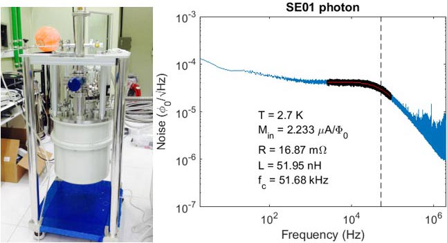
Another popular 4K test system is made with a pulse-tube refrigerator (PTR); it is called a 4K system although its base temperature reaches below 3 K. It is a dry system having a large sample space. The sample holders used for the MMC and SQUID sensors of AMoRE are typically too large to be tested in a normal storage dewar with a dipping probe. Before final assembly of the detector, all of the channels of MMC/SQUID combination, with all of bonding wires, are tested in the large sample space of this 4K system. This system also has a top loading probe for a quick test of sensor devices down to 3 K in vacuum. The cooling performances of the 4K PTR system are as follows:
- Base temperature : 2.5 K
- Cooling power at 4 K : 0.9 W
- Cool-down time of overall refrigerator from 300 K to 4 K : 4 hours
- Cool-down time with top loading probe from 300 K to 4 K : around 1.5 hours
Figure I-7 shows the PTR and a measurement done in the system for one of the channels used for the present AMoRE Pilot. It is a Johnson noise measurement confirming that sensors are active with proper inductance and normal measurement circuit resistance.
-
Figure I-7 :
PTR refrigerator (left) and a Johnson noise measurement of one of photon channels done in the PTR system.
Adiabatic Demagnetization refrigerator (ADR)
-
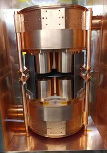
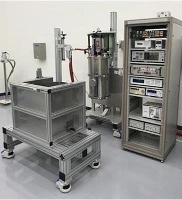
Figure I-8 :
An adiabatic demagnetization refrigerator system with lead shield
Adiabatic demagnetization refrigerators (ADRs) are a widely used refrigeration system for low temperature measurements in the 30-300 mK range. The cooling process is relatively simple. It does not require a cryogenic expert to run an ADR system. Because of adiabatic cooling, an ADR does not have a constant cooling power; it rather has a holding time in a specific temperature. It is relatively convenient system reaching below 100 mK where MMCs are active.
Our ADR (High Precise Devices, Model 103 Rainier) has a PTR with 0.7 W cooling power at 4 K. The 4K stage is often used as a test system for MMC/SQUID measurements. For mK stages, it utilizes a two-stage paramagnetic system with GGG and FAA salt pills. The cryostat of the ADR is surround by a lead radiation shield to reduce environmental gamma-ray backgrounds in detector performance tests as shown in Figure I-8. The performance figures of the ADR are as follows:
- Base temperature of FAA stage : 25 mK
- Holding time at 50 mK : 24 hours
- Cool-down time of overall refrigerator from 300 K to 3 K : 15 hours
- Cool-down time with top loading probe from 3 K to 30 mK : around 4 hours
-
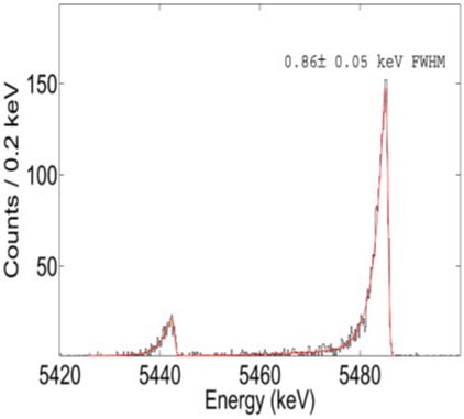
Figure I-9 :
Alpha spectrum measured in an ADR. (I. Kim et al., Supercon. Sci. Tech. 30 904005 (2017))
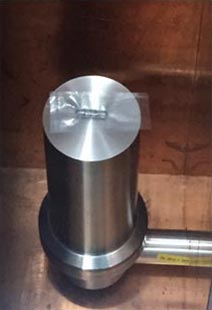
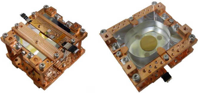
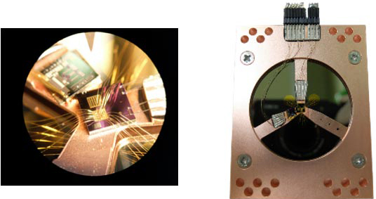
MMCs are the essential LT detector devices used in AMoRE. The energy resolutions of MMC sensors are typically investigated in the ADR as part of sensor characterization for AMoRE applications. Using one of the MMCs made by the group, an alpha spectrometers with one of the highest energy resolutions achieved was established in the ADR. Figure I-9 shows an energy spectrum showing 0.9 keV FWHM energy resolution for an external Am-241 source. It indicates the MMC detector setup and its sensitivities are suitable for 0vBB investigation. It also showed high sensitivities at low energy regions in the few keV range. Moreover, many properties of MMC sensors such as temperature-magnetization characteristics are tested in the ADR.
-
Figure I-10 :
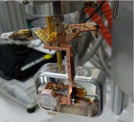
A 1 cc measurement setup attached to the ADR.
Because of its convenience, the ADR is used for crystal R&Ds. The heat and scintillation properties of various crystals have been tested for one of 1 cm3 detector system (Figure I-10) designed for an ADR measurement. Replacing many molybdate crystals such as CaMoO4, Na2Mo2O7, Li2MoO4, PbMoO4, and ZnMoO4, the 1 cc system attached to the ADR is being used for the crystal selection of the AMoRE-II experiment. It will be an important decision for the final stage of the project.
In addition, various R&D efforts have been performed in the ADR. Systematic vibration tests of light detectors were made. The present light detectors of the Pilot system were developed in the ADR. This was a crucial development to improve low frequency noise of the light signals. Moreover, in this ADR system, we studied a new type of light detector based on phonon-signal amplification using the Neganov-Luke effect. In this successful development, an amplification factor of 7 was obtained with 80 V applied to the amp voltage for the scintillation-light detection.
Dilution refrigerators (DRs)
(1) Dilution refrigerator for AMoRE-Pilot and AMoRE-I
A dilution refrigerator has been installed for physics runs of the AMoRE-Pilot and AMoRE-I experiments in a laboratory of the A5 tunnel at Y2L. We completed the whole cryogenic detector system, after renovating the A5 tunnel from scratch. We built a clean laboratory with dust and radon controls. In the lab space, we built a gantry system to support the cryostat of the refrigerator, the lead shields with moving motors, and a muon veto system composed of plastic scintillators. The complete AMoRE system required not just installation of a cryogenic system with dilution refrigerator in a gantry system, but also installation and management of necessary utilities for refrigeration and stable detector operations.
Presently, wirings of the cryostat were made for 12-channel measurement of AMoRE Pilot. When upgrading to AMoRE-I the number of channels will be increased to 36 for up to 18 crystal modules. From room temperature to the 4 K stage, copper-nickel (alloy 30) wires were used while NbTi wires with copper-nickel clads were chosen for low-temperature wirings below 4K connecting to the detector modules at 10 mK. Superconducting wires are carefully heatsinked to each temperature stage while connecting to the detector modules, minimizing heat load to lower temperature stages.
-
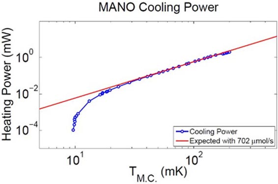
Figure I-11 :
Cooling power of the dilution refrigerator used in AMoRE-Pilot.
The base temperature has been improved with better grounding after the test.
The cryostat is being used for AMoRE-Pilot and is to be used for AMoRE-I in 2018. It was designed to host about 20 detector modules at the coldest temperature stage, each with heat and light measurement channels. It has a cylindrical experimental space in 40 cm diameter and 69 cm height. The cryostat includes an additional precooling circuit using liquid nitrogen. The precooling circuit speeds the cooling of the PTR. This setup reaches 77 K in 4 days from room temperature. It takes about a week to reach 4 K from room temperature. Condensing the He3-He4 to reach the base temperature takes less than one day. Cryogenic properties of the dilution refrigerator system are listed below.
- Base temperature: 6.5 mK
- Cooling power in normal conditions: 2 μW at 10 mK, 19 μW at 20 mK
- Maximum cooling power at 120 mK: 1.4 mW
- Cool-down time of overall refrigerator including MC lead shield from 300 K to 77 K: 4 days with liquid nitrogen precooling
- Cool-down time of overall refrigerator including mixing-chamber lead shield from 77 K to 4 K: 2 days
- Cool-down time from 40 K to 10 mK: 8 hours
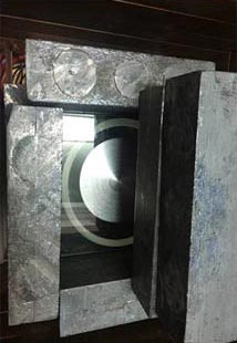
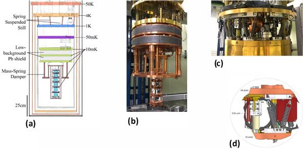
The cryostat with a dilution refrigerator unit is made of normal low temperature materials. The parts of the supporting structure and refrigerator were not selected for certain radio-purity levels. However, the copper plates of each temperature stage are made of NOSV-grade (Aurubis brand) copper. Moreover, the IR shielding cans are made of NOSV copper. To reduce the gamma radiation from the cryogenic parts above the mixing chamber (MC) plate, a total 10 cm thickness (170 kg) of low activity lead bricks are attached to the bottom of the MC plate as shown in Figure I-12.
In early stages of the Pilot measurement, we found the signals suffered from machine vibration originating from its PTR operation. We introduced two-stage vibration mitigation systems. The first vibration damping system so called mass spring damper (MSD) is made with a set of springs connecting the MC and the detector tower. Another system isolates the still plate from the 4 K plate using heavy duty springs, creating a so called spring suspended still (SSS), after replacing original connections with soft ones. Eddy current dampers provides efficient damping mechanism to reduce low frequency noise in the detector signals. With the two damping systems, the energy resolution of Pilot detectors was improved to 8.7 keV FWHM from 40 keV FWHM for 2.6 MeV gamma rays. Figure I-12 shows the assembly of the MSD and SSS system in the refrigerator.
-
Figure I-12 :
(a) Schematic view of dilution refrigerator and the detector setup in AMoRE-pilot. (b) Picture of the cryostat including MSD and the detector tower of AMoRE-pilot. (c) SSS installed between 4 K and still plate. (d) Schematics of SSS and the eddy current damper.
(2) R&D dilution refrigerators
-
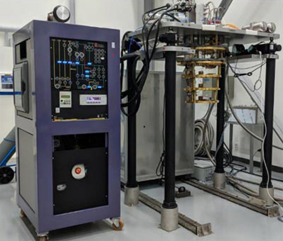
Figure I-13 :
Dilution refrigerator installed in the HQ lab
One of most important decisions for AMoRE-II preparation is crystal selection. AMoRE Pilot and AMoRE-I use mainly 40Ca100MoO4 crystals. Because of the cost 40Ca, other candidate crystals are under investigation using R&D dilution refrigerators. One system was installed at the KT1 laboratory, and has recently been moved to the permanent place at the HQ laboratory as shown in Figure I-13. A systematic survey of full size molybdate crystals are to be tested in the cryostat with the proper MMC and SQUID setup. The crystal R&D does not require underground measurements. However, checks of internal background for AMoRE II will be performed in another refrigerator installed in Y2L having the same size and cooling power as the system at HQ. Installation of this system is also completed. Moreover, the underground refrigeration system is to be used for a dark-matter search R&D program. In particular, the study will target low-mass dark mater detection. The detection limit is to be investigated with crystal detectors and Si absorbers with the Neganov-Luke phonon amplification feature.
- Base temperature: 9 mK
- Cooling power in normal conditions: 1 μW at 10 mK, 10 μW at 20 mK
- Maximum cooling power at 120 mK: 700 mW
- Cool-down time of overall refrigerator including MC lead shield from 300 K to 77 K: 3 days without liquid nitrogen precooling
- Cool-down time of overall refrigerator including MC lead shield from 77 K to 4 K: 1 day
- Cool-down time from 40 K to 10 mK: 8 hours
Fabrication (Fab) Facility
CUP specializes in production of MMC sensors and detector modules for various applications. In particular, MMCs are used as the key technology for the thermal calorimetric detection for the AMoRE project. The heat (phonon) and light (scintillation photon) detectors are developed using cleanroom technologies. A CUP micro-fabrication facility and related equipment are needed for two main purposes. One is MMC production as these are the core sensors of the calorimetric detection of CUP projects. The other purpose is to make phonon collectors on crystal surfaces. Phonon collectors are metal films on a dielectric crystal surface, and are required for efficient heat transfer between an absorber crystal and an MMC sensor. Both of MMC production and phonon collection fabrication should be done using designated equipment with specific design and procedures.
MMC production was developed on the basis of superconducting sensor fabrication. It also requires magnetic material deposition in a high-vacuum environment and thick gold electro-deposition. MMCs are not commercially available at the moment although several world-wide institutions including IBS-CUP are capable of producing them. CUP designed optimal MMCs used in the AMoRE project to employ detector modules with an absorber crystal of 300-500 g mass. Some MMC features necessary for AMoRE project are realized only in the IBS laboratory.
AMoRE searches for extremely rare events using crystal absorbers. The radio purity of AMoRE crystals should be given special considerations during every step including the handling of raw materials, crystal growing procedures, and assembling procedures for detector modules. The crystals may not be exposed to normal laboratory conditions in which Rn gas may be adsorbed on their surface. A glove box and an air-tight transport container is required while handling crystals. A special evaporator with a series of load-lock systems is necessary to be used for phonon-collector deposition for this purpose. On the other hand, fabrication of light detectors uses similar clean-room procedures as phonon-collector deposition on the main crystal.
MMC fabrication requires 11 steps of micro fabrication in a cleanroom. We installed several pieces of fabrication equipment in established clean rooms. They are mainly used for deposition and patterning for superconductors, metals and insulators. Because the number of measurement channels needed for the AMoRE project is more than 1000, the production yield is another important parameter in the chip production line. We describe three pieces of major fabrication equipment installed in our cleanrooms as follows.
-
Figure I-14 :
CUP sputter installed in class-1000 clean room
(1) Sputters (Figure I-14)
- Use : Metal, Superconductor deposition
- Available targets : Nb, Au:Er, Au, Ti, Cr
- Main features : This is the main deposition chamber for Nb superconductor, gold, and MMC sensor material (Au:Er). The main process chamber hosts five sets of DC sputtering guns. Each sputter system has its own valve on-off from the main chamber to prevent cross contamination between target materials. Two guns specified for Au:Er and Au deposition are configured for confocal co-sputtering to adjust Er concentration for an optimal condition. The substrate holder rotates the wafer, and is cooled water cooled. A load-lock camber is attached to the main chamber to maintain the high vacuum condition. An RF sputter is installed in the load-lock chamber, mainly to etch out an oxidized metal layer before processing is performed in the main chamber.
-
Figure I-15 :
E-beam evaporator designed to load 4 AMoRE crystals
(2) E-beam evaporator (Figure I-15)
- Use : Metal (phonon-collector) deposition
- Available source : Au, Ag, Ti, Cr
- Main features : Thin metal layers with high electric conductivity can be fabricated in this chamber. One of important features of this e-beam evaporator is crystal handling in two step load-lock systems. The first one is a vacuum load-lock in which motor driven crystal loaders move in and out of the main chamber. The second one is a glove box connected to the vacuum load-lock. A crystal carrying container is opened in order to load crystals onto a tray in the vacuum load-lock in a controlled environment. The glove-box load lock is used to clean crystal surfaces with solvent just before phonon-collector deposition. The main chamber of the e-beam evaporator is divided with a gate valve into a source chamber and a substrate chamber. The source chamber can be open to the air, keeping the substrate chamber in vacuum while replacing or adding deposition sources. The substrate holder in the main chamber was designed to load four crystals with total mass of 2 kg. The holder rotates, and is water cooled.
(3) ICP-RIE (Inductive Coupled Plasma – Reactive Ion Etcher)
- Use : Etching metal layers to pattering micro structures
- Available gas : SF6, Ar, O2
- Main features : When our detector operates at low temperatures, MMCs work by running persistent supercurrent on their chip die. The critical current of micro patterned Nb coil is one of most important parameters for successful MMC fabrication. The ICP-RIE specializes etching a thick metal layer with high vertical aspect ratio. This feature ensures a constant width of the long Nb pattern. Dense plasma is produced from a tornado coil electrode in the main chamber of the ICP-RIE. An electrostatic wafer chuck is chosen for efficient substrate cooling. Samples are loaded through a load-lock. The first pattering process of Nb film is made in the ICP-RIE chamber for the MMC fabrication.
(4) Class 100 and 1000 clean room
We established class 100 and 1000 clean rooms at the KT1 laboratory as temporary lab space available for our fabrication work. Below are pictures of the cleanrooms. We have also been setting up new clean rooms in the permanent IBS headquarter building for continuing micro fabrication.
-
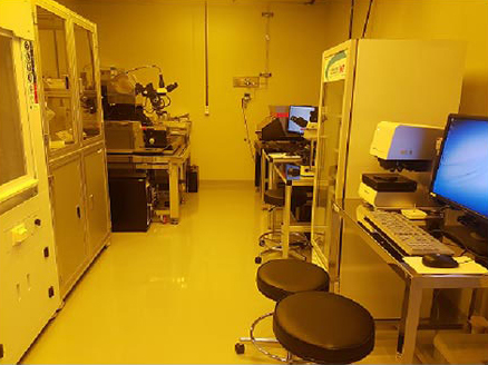
100 class (yellow room)
-
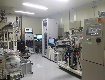
1000 class
(5) List of fabrication equipment
Fabrication facility
| Metal thin film system | Metallic magnetic calorimeter sputtering system |
| Radon free environment e-beam evaporator system | |
| Pattern lithography equipment | Maskless Micro Pattern Generator |
| Dual Focus Micro-Pattern Mask Aligner | |
| Metal film etching equipment | ICP-RIE (Inductively Coupled Plasma- Reactive Ion Etching) system |
| Insulation film growth equipment | LT-PECVD (Low-Temperature Plasma-enhanced chemical vapor deposition) |
| Anodizing unit | |
| Thick Au layer fabrication | Simple electroplating unit |
| Chip dicing | Dicing saw |
| Resist coating unit | Spin coating system Hot plate |
| Fabrication step verification | 3D Measuring Laser Microscope |
| Optic Microscope | |
| Collector annealing system | Rapid thermal process system |
(6) Fabrication results
Example of fabrication results completed in the laboratories
-
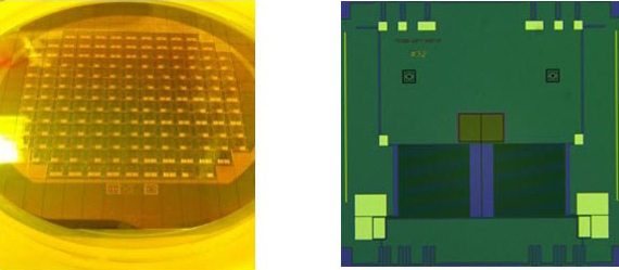
Completed 3 inch wafer and an MMC die
-
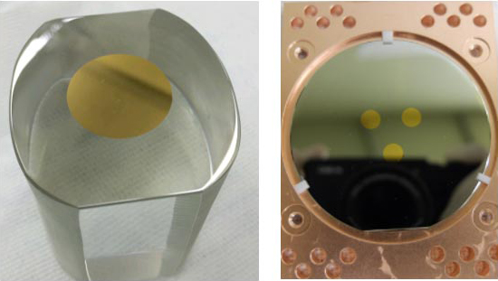
Phonon-collector film evaporated on a crystal surface
and a light detector wafer
-
Assembled heat sensor
-
Light detector assembly
NaI Crystal Growing Facility
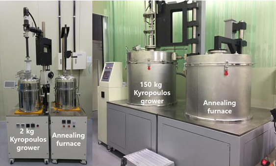
Two sets of Kyropoulos (KY) crystal growers for NaI:Tl crystal growth (Figure I-18) were installed. Each set consists of a grower and an annealing furnace. A small test grower can charge about 2 kg of NaI powder and a large grower, which is for growing the real COSINE detector, can charge 150 kg of NaI powder (Table I-1). These growers were designed with Dr. Alain Iltis, a former employee of Saint-Gobain who made NaI crystals for the DAMA/NaI experiment.
-
Figure I-18 :
Kyropoulos crystal growers, KY01 (left) and KY02 (right)
Table I-1 : Characteristics of growers
| Name | Max temp | Zone | Dimension of Crucible | Max load | Remarks |
|---|---|---|---|---|---|
| 2 kg KY grower | 800 ℃ | 3 zone | Φ120 mm × 135 mm | 2 kg | Test grower |
| 2 kg furnace | 800 ℃ | 2 zone | - | As-grown NaI | Annealing |
| 150 kg KY grower | 800 ℃ | 3 zone | Φ611 mm × 440 mm | 150 kg | For the COSINE |
| 150 kg furnace | 800 ℃ | 2 zone | - | As-grown NaI | Annealing |
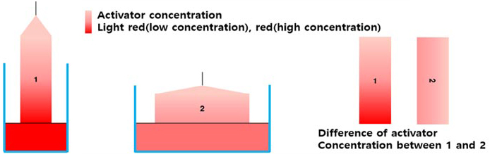
NaI and TlI are very volatile materials when melted, and crystal growth has a tendency to push impurities back to melt, so it is difficult to make an optimum concentration of Tl(activator) and minimize Tl concentration difference between the top and bottom of a crystal. Conventional crystal growth methods produce a long height and a comparably narrow diameter (Figure I-19 (1)), so the Tl concentration difference between top and bottom is quite large. Our grower can grow short and wide-diameter (Figure I-19 (2)) crystals. This method can reduce concentration difference between top and bottom, so we can get quite uniform scintillation properties with our NaI:Tl crystals grown at CUP. For optimum concentration, we have to exercise the process several times to obtain good growing conditions and reduce growth time.
-
Figure I-19 :
Comparison of concentration between conventional growth method (1) and CUP’s growth method (2)
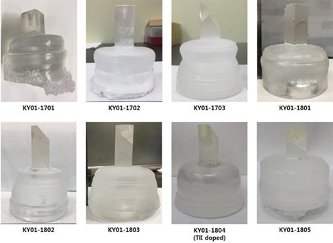
We are testing to grow small NaI crystals with the 2 kg Kyropoulos grower and have so far grown eight NaI crystals. Figure I-20 shows the grown NaI crystals, seven are pure NaI and one is 0.1 mol% Tl doped NaI crystal. There were minor issues like bubbles, a central hole, and contamination issues, but some of them were resolved. We need to improve growing conditions of NaI more. CUP-grown NaI crystals were measured with ICP-MS and results are summarized in Table I-2. KY01-1701 and 1702 were grown with the crystal grade NaI powder (Sigma Aldrich, >5N) and from KY01-1703 to 1804 were grown with the Merck NaI powder (4N). The ICP-MS result of KY01-1701 showed quite severe contaminations from quartz felt, so we no longer use quartz felt. In the rest of grown crystals, there are no observable contaminations. We can observe significantly good reduction of impurities in molybdate crystals for the AMoRE experiment but not for NaI crystals. Therefore, highly purified NaI powders are necessary.
-
Figure I-20 :
Grown NaI crystals
Table I-2: ICP-MS results of the grown NaI crystals
| Sample | Al(ppb) | k(ppb) | Sr(ppt) | Ba(ppt) | Tl(ppm) | Pb(ppt) | Th(ppt) | U(ppt) |
|---|---|---|---|---|---|---|---|---|
| Raw powder (Sigma-Aldrich, Crystal grade) |
55 | 57 | 720 | 5,637 | – | 2,019 | 4.39 | <3 |
| Quartz felt (Saint-Gobain) |
1,463 | 7,362 | 3,200 | 136,000 | – | 72,000 | 500 | 1,000 |
| KY01-1701 (w/ quartz felt) |
106 | 6,460 | 1,042 | 2,757 | – | 17,640 | <4 | <5 |
| KY01-1702 | 216 | <79 | 470 | 3,730 | – | 1,436 | <4 | <6 |
| Seed crystal (EPIC) |
227 | 1,003 | 38,102 | 1,229,322 | 944 | 5,356 | 5.54 | 9.09 |
| Raw powder (Merck, 99.99 %) |
145 | 248 | 19,020 | 2,880 | 1.68 | 39,959 | <6 | <6 |
| KY01-1703 | 172 | 276 | 7,957 | 2,020 | – | – | <6 | <6 |
| KY01-1801 | 144 | 308 | 14,282 | 1,571 | – | 55,616 | <6 | <6 |
| KY01-1803 | 168 | 136 | 12,509 | 1,335 | 0.15 | 37,276 | <6 | <6 |
| KY01-1804-T (NaI:Tl) |
186 | 189 | 4,512 | 1,274 | 716 | 40,568 | <6 | <6 |
| KY01-1804-B (NaI:Tl) |
205 | 566 | 2,833 | 4,132 | 1.630 | 42,715 | <6 | <6 |
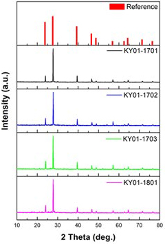
Figure I-21 shows XRD analysis results of four CUP-grown NaI crystals and all crystals are well crystallized.
-
Figure I-21 :
XRD analysis results of NaI crystals
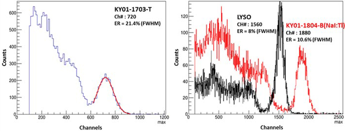
The KY01-1703 and KY01-1804 crystals are cut and polished to measure scintillation properties. Polishing and measuring were done in a glove box in a nitrogen atmosphere. Figure I-22 shows pulse-height spectra of NaI crystals irradiated by 662 keV gammas from a 137Cs source. The light yield of a reference LYSO crystal is 33,000 ph/MeV, and the KY01-1703 (pure NaI) shows a light yield of ~3,000 ph/MeV. In case of the Tl doped NaI (KY01-1804) crystal, the light yield is ~40,000 ph/MeV. Typical Tl doped NaI shows about 40,000 ~ 50,000 ph/MeV.
-
Figure I-22 :
Pulse height spectra, pure NaI (left), NaI:Tl (right)
We have practiced the technique many times to grow good quality NaI crystals. We expect that we soon can be ready for growing large NaI crystals with the 150 kg grower (KY02). Our goal with the large NaI crystal grower is to grow 115 kg of crystals with dimensions of Φ400 mm × 250 mm.
Oxide Crystal Growing Facility
Crystal Growers
So far, we have 2 Czochralski crystal growers (Table I-3, Figure I-23) for the AMoRE experiment. Their purpose is to grow high purity CaMoO4, Li2MoO4, and Na2Mo2O7 crystals from highly purified powder. Contamination is a very important issue for the AMoRE experiment, so we are using two growers for growing CaMoO4 (CZ01) and Li2MoO4 (CZ02) crystals separately. In the next year, a new Czochralski crystal grower will be installed for growing Na2Mo2O7 crystals. All growers are equipped with high-resolution load cells (can measure 1/10000 g of crystal weight) and computerized control systems. The growing process is controlled by a computer based on input crystal shape parameters.
Table I-3: Properties of growers
| Grower | Max temp | Crucible | Remarks | ||
|---|---|---|---|---|---|
| Material | Dimension | Max load | |||
| CZ01 | 1600 ℃ | Iridium | Φ10 × 10 cm3 | ~ 3 kg | For CaMoO4 |
| CZ02 | 1600 ℃ | Platinum | Φ10 × 10 cm3 | ~ 2.5 kg | For Li2MoO4 |
-
Figure I-23 :
The Czochralski crystal grower, CZ01 (left) and CZ02 (right)
CaMoO4 crystal growth
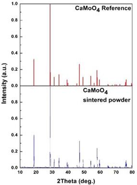
From 2014 to 2016, we tried to grow CaMoO4 crystals with the CZ01 grower. Raw CaMoO4 powder was synthesized by solid-phase reaction with CaCO3 and MoO3 powders (99.95 %, Alfa Aesar). Sintered powder was measured by an XRD, and the XRD analysis result (Figure I-24) matched well with reference CaMoO4 material.
-
Figure I-24 :
XRD analysis result of sintered CaMoO4 powder
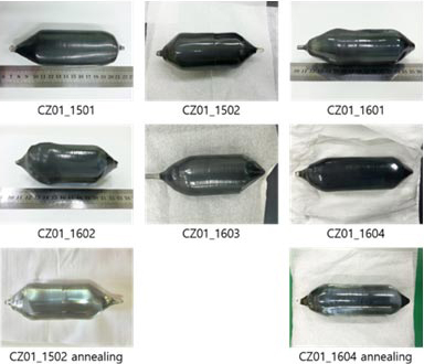
Six CaMoO4 crystals were successfully grown by the CZ01 grower with an iridium crucible. CUP-grown CaMoO4 crystals are shown in Figure I-25 with their properties listed in Table I-4. The crystals are rectangular because the crystal system is tetragonal. Oxygen deficiency causes the dark blue color. After annealing the crystals in the air (Figure 1-25, CZ01-1502 and 1604 after annealing), then the dark blue color was almost gone but a yellowish tint appeared because of impurities.
-
Figure I-25 :
The grown CaMoO4 crystals by the CZ01 grower
Table I-4: Information of grown CaMoO4 crystals
| Crystal No. | Weight | Total Length | Body length | Diameter | Remarks |
|---|---|---|---|---|---|
| CZ01-1501 | 520 g | 13 cm | 7 cm | 3.4 ~ 4.4 cm | Used as seed |
| CZ01-1502 | 800 g | 15 cm | 7 cm | 4.5 ~ 5.1 cm | - |
| CZ01-1601 | 800 g | 16 cm | 7 cm | 4.6 ~ 5.1 cm | - |
| CZ01-1602 | 790 g | 16 cm | 7 cm | 4.3 ~ 5.5 cm | - |
| CZ01-1603 | 740 g | 19 cm (plan) | 10 cm (plan) | 4.4 ~ 5.2 cm | broken |
| CZ01-1604 | 1050 g | 19 cm | 10 cm | 4.4 ~ 5.2 cm | - |
Sintered powder and CUP-grown crystals were measured with ICP-MS to study impurities. The results (see Table I-5) show that all impurities are reduced in CaMoO4 crystals. The reduction factors for K and Fe are about 100, and that for Th and U are about 20 and 70 respectively. Even though the crystals show good reduction factors, the final result is not good enough for the AMoRE experiment yet. At that time we used low-purity powder (99.95 %). Now we can use commercial MoO3 powders which have been further purified through sublimation by our chemical team. With the purified MoO3 powders, the impurity level of CaMoO4 crystals can be further reduced.
Table I-5: ICP-MS results of CaMoO4 crystals and sintered powder (unit is ppb)
| C. No. | K | Cr | Fe | Zr | Ir | Pt | Al | Sr | Ba | Pb | Th | U |
|---|---|---|---|---|---|---|---|---|---|---|---|---|
| Powder | 41,914 | <30 | 132,737 | 893 | <1 | <0.3 | 44,008 | 68,289 | 2,382 | 228 | 32 | 629 |
| 1502 | - | - | - | 15.8 | 5.5 | <10 | <662 | 51,368 | 121 | 12.9 | 1.3 | 7.9 |
| 1601 | 471 | <30 | 1,261 | 19.0 | 5.0 | 2.2 | 160 | 90,556 | 137 | <1 | 1.5 | 9.0 |
| 1604 | 439 | 24 | 1,475 | 18.8 | 6.1 | 0.2 | <60 | 59,413 | 116 | 6.6 | 1.3 | 9.3 |
Li2MoO4 crystal growth
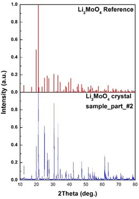
Another candidate crystal for the AMoRE experiment is Li2MoO4 crystal. For crystal growth, we tried to sinter Li2CO3 and MoO3 powders by solid-phase reaction, as for the sintered CaMoO4 powder, but we could not obtain sintered Li2MoO4 powder. By mixing Li2CO3 and MoO3 powders and melting them in a platinum crucible in the CZ02 grower, we were able to grow Li2MoO4 crystal. Figure I-26 shows XRD analysis results of the CUP-grown Li2MoO4 crystal, and it is well matched with a reference crystal.
-
Figure I-26 :
XRD analysis result of Li2MoO4 crystal
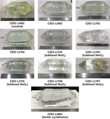
Figure I-27 and Table I-6 show information about CUP-grown Li2MoO4 crystals. We used Li2CO3 powder (99.998%, Alfa Aesar) for all the crystals. From CZ02-L1601 to CZ02-L1702, we used MoO3 powders of 99.95% purity from Alfa Aesar. Because of the low purity of the powders, the colors of the Li2MoO4 crystals are yellowish. From CZ02-L1703 to CZ02-L1707, we used sublimated MoO3 (> 99.999% purity) and the colors of crystals are less yellowish. The CZ02-L1801 crystal was double crystallized, meaning it was grown with material recycled from previous CUP-grown crystal (CZ02-L1704, L1705, L1706 and L1707).
-
Figure I-27 :
The grown Li2MoO4 crystals
Table I-6: Information of grown Li2MoO4 crystals
| Crystal No. | Weight | Total length | Body length | Diameter | Remarks |
|---|---|---|---|---|---|
| L1601 | 470 g | 14 cm | 5 cm | 4.8 ~ 5.2 cm | Cracked |
| L1602 | 600 g | 14 cm | 7 cm | 5.0 ~ 5.1 cm | - |
| L1701 | 590 g | 14 cm | 7 cm | 4.6 ~ 5.2 cm | - |
| L1702 | 590 g | 14 cm | 7 cm | 4.8 ~ 5.2 cm | - |
| L1703 | 592 g | 14 cm | 7 cm | 5.0 ~ 5.2 cm | Sublimed MoO3 |
| L1704 | 573 g | 13 cm | - | 5.1 ~ 5.2 cm | Sublimed MoO3 failed |
| L1705 | 648 g | 15 cm | 8 cm | 4.8 ~ 5.1 cm | Sublimed MoO3 |
| L1706 | 657 g | 15 cm | 8 cm | 4.8 ~ 5.1 cm | Sublimed MoO3 |
| L1707 | 641 g | 14 cm | - | 5.0 ~ 5.1 cm | Sublimed MoO3 failed |
| L1801 | 580 g | 14 cm | 7 cm | 5.1 ~ 5.5 cm | D/C |
The CUP-grown Li2MoO4 crystals were measured with ICP-MS (Table I-7) and HPGe (Table I-8) in order to study general and radioactive impurities respectively. We did not sinter Li2MoO4 powder, so we cannot directly compare impurity levels of the powder with those of the crystal. ICP-MS results show all impurities significantly reduced. With the exception of Ba, all measured impurities of double-crystallized L1801 crystal were below the detection limit. Radioactivity of 40K in L1602 is about 30 mBq/kg, and the others are below detection limits. All the radioactive impurities are below the detection limits for both L1703, which was grown with sublimated MoO3, and for the double-crystallized L1801
Table I-7: ICP-MS results of grown Li2MoO4 crystals and powders
| C. No. | Element [ppt] | ||||||||
|---|---|---|---|---|---|---|---|---|---|
| K | Rh | Zr | Al | Sr | Ba | Pb | Th | U | |
| Li2CO3 99.998 % |
314,524 | <1,000 | 3,283 | 414,878 | 8,133 | 104,045 | 21,637 | <10 | 615 |
| MoO3 99.95 % |
- | - | - | - | 23,714 | 2,829,035 | 107,027 | 91 | 7014 |
| MoO3 sublimed |
- | - | - | - | 1,670 | 255,652 | 66,893 | <100 | 1,080 |
| L1601 | 529,568 | <550 | <100 | 16,802 | <15 | 5,612 | <300 | <15 | <16 |
| L1602 | 264,578 | <550 | <100 | 25,173 | <15 | 5,167 | <300 | <15 | <16 |
| L1701 | 347,302 | <550 | <100 | 48,145 | <15 | 5,445 | <300 | <15 | <16 |
| L1702 | 478,174 | <550 | <100 | 36,481 | <15 | 6,243 | <300 | <15 | <16 |
| L1704 Sublimed MoO3 |
107,897 | <1,200 | <100 | 39,212 | 758 | 7,080 | <333 | <10 | <10 |
| L1705 Sublimed MoO3 |
<30,000 | <1,000 | <100 | <20,000 | 1,005 | 28,474 | <300 | <9 | <9 |
| L1706 Sublimed MoO3 |
38,000 | <800 | <300 | <11,000 | <50 | 7,579 | <100 | <8 | <8 |
| L1707 Sublimed MoO3 |
39,000 | <800 | <300 | <11,000 | <50 | 6,300 | <100 | <8 | <8 |
| L1801 D/C |
<30,000 | <800 | <300 | <11,000 | <50 | 4,744 | <100 | <8 | <8 |
Table I-8: HPGe result of Li2MoO4 crystal and powder (unit is mBq/kg)
| Crystal No. | 238U | 40K | 228Ac | 228Th |
|---|---|---|---|---|
| Li2CO3 99.998 % |
0.95±0.22 | 9.0±3.4 | 1.4±0.64 | 0.41±0.22 |
| MoO3 99.95 % |
2,022±180 | 1,090±220 | 460±60 | 145.06±13.74 |
| MoO3 Sublimed |
189.0±17.3 | 73.8±17.6 | 44.9±7.8 | 18.1±2.5 |
| L1602 With 99.95 % MoO3 |
<3.28 | 28.9±9.7 | <2.63 | <1.51 |
| L1703 With sublimed MoO3 |
<0.55 | <8.15 | <2.10 | <0.92 |
| L1801 Double crystallization |
<1.2 | <13.8 | <3.2 | <1.3 |
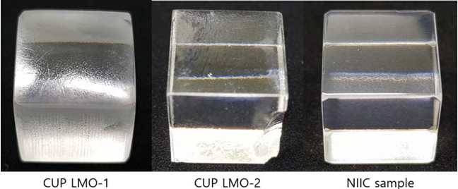
Recently, we have tested lapping and polishing crystals and Figure I-28 shows polished 1cm3 Li2MoO4 crystals. We tried many different kinds of sanding and polishing materials. So far, using colloidal silica for final polishing shows very good polishing performance but some micro scratches of surface are remaining. We are planning to lap crystals with finer sanding papers
-
Figure I-28 :
Lapped and polished 1 cm3 Li2MoO4 crystals
Na2Mo2O7 crystal growth
-
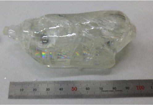
Figure I-29 :
The grown Na2Mo2O7 crystal (CZ02-N1701, 260 g)
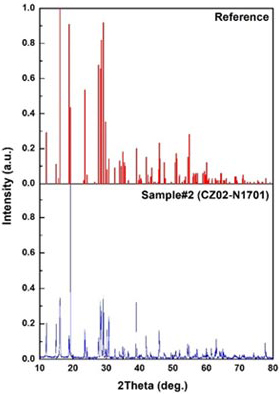
We initially tried to grow Na2Mo2O7 crystal with the CZ02 grower using 99.997 % Na2CO3 and sublimated MoO3, but were barely able to produce one cracked crystal (Figure I-29). Na2Mo2O7 crystal has multiple cleavage planes, so crystals cracked in every trial and fell down to the melt. The NIIC (Nikolaev Institute of Inorganic Chemistry), an institution collaborating with AMoRE on crystal growth, also tried to grow Na2Mo2O7 crystals more than 50 times, but they succeeded for only a few crystals. We will not have an additional Czochralski grower dedicated to Na2Mo2O7 crystal growth until 2019. This crystal is severely affected by thermal stress, so the new CZ03 grower will have reinforced thermal shielding to heat inside of the hot-zone. Figure I-30 and Table I-10 show XRD and impurities results of Na2Mo2O7 crystal. The XRD pattern is well matched with the reference. The impurities are quite reduced in CUP-grown crystal, but they are comparatively higher than impurities in the Li2MoO4 crystals. It looks like we need more purification of the raw powders or double crystallization.
-
Figure I-30 :
XRD analysis result of grown Na2Mo2O7 crystal
Table 1: ICP-MS result of grown Na2Mo2O7 crystal
| Crystal No. | Element [ppt] | ||||
|---|---|---|---|---|---|
| Sr | Ba | Pb | Th | U | |
| Na2CO3 | 22,003 | 75,174 | 267,648 | <52 | <52 |
| Sublimed MoO3 | 1,670 | 255,652 | 66,893 | <100 | 1,080 |
| N1701 | 3,928 | 11,908 | 31,333 | <23 | <23 |
| LMO1 from NIIC | 476,184 | 8,713 | 5,711 | <23 | <23 |
| LMO2 from NIIC | 729,837 | 9,353 | 6,615 | <23 | <23 |
 Center for Underground
Physics (CUP)
IBS Center for Underground Physics, IBS, Experiment building, 1st floor, 55, Expo-ro, Yuseong-gu, Daejeon, Korea (34126)
Copyright(c) Center for Underground Physics at IBS.
All Rights Reserved.